Download Links: Siemens SIMATIC STEP 7 Professional 2017 (STEP 7 v5.6 + S7-PLCSIM v5.4 SP8 + S7-SCL v5.6 + S7-GRAPH v5.6 + S7-PCT v3.4 HF2) x64 + Crack Copy the download link and paste to your browser. Ine ccie security v5 workbook.
[Download] SIEMENS SIMATIC STEP 7 v5.6 Proffesional + Crack aHR0cDovL2Rvd25hcmNoaXZlLm9yZy9zb2Z0d2FyZS9ncmFwaGljcy1hbXAtZGVzaWduLzMyMTQ4LXNpZW1lbnMtc2ltYXRpYy1zdGVwLTctdjU2LXByb2ZmZXNpb25hbC5odG1s DECODE HERE: www(.)base64decode(.)org.You then get a link download!! Description: STEP 7 is a basic software package that includes the tools required for programming and operating control systems based on the SIMATIC S7 / C7 programmable controllers, as well as the SIMATIC WinAC computer control systems.

A distinctive feature of the STEP 7 package is the possibility of developing complex automation projects based on the use of a number of programmable controllers, industrial computers, devices and systems of the human-machine interface, distributed input-output devices, industrial communication network structures. Restrictions on the development of such projects are superimposed only on the functionality of programmers or computers on which STEP 7 is installed.
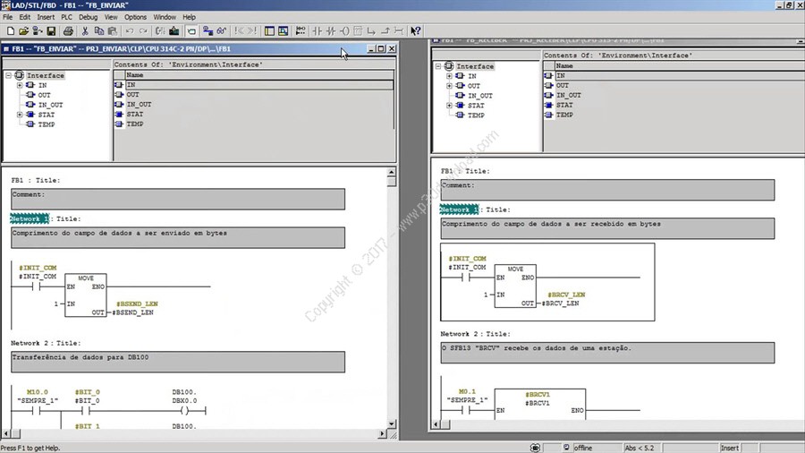
ScreenShots: Software Description: Siemens SIMATIC STEP 7 software is theprofessional tool for the SIMATIC S7, SIMATIC C7 and SIMATIC WinACautomation systems. It enables the user to use the performancecapability of these systems easily and conveniently. SIMATIC STEP 7 contains convenient functions for all phases of anautomation project: – Configuring and parameterizing the hardware – Specifying the communication – Programming – Test, start-up and service – Documentation, archiving – Operating/diagnostics functions SIMATIC STEP 7 program tools: 1.

SIMATIC-Manager: The SIMATIC Manager manages all data belonging to an automationproject, regardless of the target system (SIMATIC S7, SIMATIC C7 orSIMATIC WinAC) on which they are implemented. It provides a common entry point for all SIMATIC S7, C7 or WinACtools. The SIMATIC software tools that are necessary for processingthe selected data are automatically started by SIMATIC Manager. Symbol-Editor: With the tool Symbol Editor all global variables (in contrast tothe local formal parameters that are declared when the blocks areprogrammed) are managed.
The following functions are available: – Definition of symbolic designations and comments for the processsignals (inputs/outputs), flags and blocks – Sorting functions – Data exchange with other Windows programs The symbol charts that are generated when this tool is used areavailable to all software products. Changes to a symbol parameterare therefore automatically recognized by all tools. Hardware configuration: The tool Hardware Configuration is used for configuring andparameterizing the hardware used for an automation project. Thefollowing functions are available: – Configuration of the automation system Racks are selectedfrom an electronic catalog and the selected modules are assigned tothe required slots in the racks. – The configuration of the distributed I/Os is done in the same wayas the configuration of the non-distributed I/Os; channel-granularI/O modules are also supported.
– CPU parameter assignment: Properties such as restart characteristics and cycle-timemonitoring can be set menu-driven. Multicomputing is supported. Theentered data are filed in system data blocks in the CPU. – Module parameter assignment: The user can specify all the adjustable parameters of the modulesin input screen forms. Adjustments via DIP switches becomeunnecessary. Parameterization of hardware modules occursautomatically during the CPU’s acceleration.
Thus, a change of amodule can be made without another parameterization. – Function module (FM) and communications processor (CP) parameterassignment: This parameterization also occurs within the hardware configurationin the same way as the parameterization of the other modules. Forthis parameterization hardware-module-specific screen forms andrules are provided for each FM and CP (is included in the FM/CPfunctions package). The system prevents faulty inputs by offeringonly allowed entry options on the parameter assignment screenforms.
Communication configuration: – Configuring and display of communication links – Time-driven cyclic data transmission via MPI: – Selection of communication partners – Entering of data source and data destinationin a table.Generation of all system data blocks (SDBs) to be loadedand their complete transmission to all CPUs take placeautomatically – Parameterization of the selected communicationblocks in the customary programming language (e.g., LAD). – Event-driven data transmission – Definition of the communication links. – Selection of the communication function blocks (CFBs) from theintegrated block library. – Parameterization of the selected communication blocks in thecustomary programming language (e.g., LAD). System diagnostics: System diagnostics offer the user an overview of the status of theautomation system. The display can be in two different forms: – Display of text messages, which can be output directly andquickly.